Introduction
Hydraulic pump failures rarely announce themselves. A pump can appear operational—turning, humming, cycling—while internally bypassing fluid at a rate that silently degrades system performance and accelerates component wear. By the time operators notice sluggish actuators or inconsistent pressure, the damage is done. Undetected pump wear causes unplanned downtime, which costs manufacturing facilities $50,000 to $200,000 per hour and construction fleets $500 to $1,000+ per hour. Emergency repairs carry a 150-200% cost premium over planned maintenance.
Hydraulic pump testing is a systematic process of measuring a pump's flow, pressure, and efficiency under load to determine whether it is performing to specification or has degraded to the point of failure.
This guide is written for maintenance technicians, equipment operators, and fleet managers working with construction, agricultural, and industrial hydraulic machinery. You'll learn:
- The full testing process, step-by-step
- What measurements to take and how to read them
- What factors affect test accuracy
- When a pump's condition warrants professional intervention
Key Takeaways
- Hydraulic pump testing determines whether a pump maintains rated flow under operating pressure, the most reliable indicator of pump health
- Core testing methods include the relief valve flow test, case drain flow monitoring, motor current draw tracking, and bench testing
- A pump that delivers full flow at low pressure but loses flow as pressure increases is internally worn and likely needs repair or replacement
- Pre-test safety steps—pressure relief, PPE, and visual inspection—are required before any diagnostic measurement is taken
- When field testing confirms internal failure, a professionally rebuilt exchange unit is often the fastest path back to operation
What Is Hydraulic Pump Testing and Why It Matters
Hydraulic pump testing is the process of evaluating a pump's volumetric efficiency, pressure output, and flow rate under controlled or real operating conditions to determine whether it meets manufacturer specifications. According to ISO 4409, volumetric efficiency is defined as the ratio of actual output flow to theoretical flow at a given shaft speed and pressure.
Why Testing Differs from Visual Inspection
A pump can appear operational while internally bypassing fluid, delivering insufficient flow, and silently degrading system performance. Only load-based measurement reveals the true condition. Visual checks and runtime observations cannot detect:
- Internal seal wear that allows high-pressure fluid to leak across worn tolerances
- Piston or vane surface degradation that reduces volumetric efficiency
- Bearing clearances that permit internal bypass without external leakage
- Compensator drift in variable-displacement pumps
The Cost of Skipping Testing
The financial stakes are substantial:
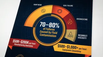
- Manufacturing facilities lose $50,000–$200,000 per hour of unplanned downtime
- Construction and heavy equipment operations lose $500–$1,000+ per hour
- Emergency hydraulic repairs carry a 150–200% cost premium over planned maintenance
Beyond downtime costs, fluid contamination causes 70–80% of all hydraulic system failures. Replacing a pump without testing can leave the root cause unaddressed, leading to repeat failures and compounding costs. A systematic test takes minutes and confirms whether the pump is the actual failure point before any parts are ordered or swapped.
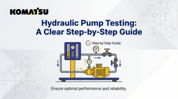
How to Test a Hydraulic Pump: Step-by-Step
Four primary testing methods are used across the industry:
- Relief valve flow test
- Case drain flow and temperature monitoring
- Motor current draw tracking
- Bench testing
Use these individually or in combination depending on access, equipment, and required precision.
Step 1: Pre-Test Safety and Setup
Before any testing begins, follow these required safety steps:
- Relieve all system pressure by cycling actuators and venting accumulators
- Lock out/tag out the power source to prevent accidental startup
- Wear appropriate PPE (gloves, safety glasses, hearing protection)
- Ensure a proper workspace with adequate ventilation and spill containment
Pressurized hydraulic fluid injection injuries are severe—fluid under 3,000+ psi can penetrate skin and cause tissue necrosis. Never use bare hands to search for leaks. Use cardboard or paper to detect leaks safely.
Step 2: Visual and Auditory Inspection
Before connecting any instruments, check:
Visual inspection:
- Casing condition for cracks, dents, or external damage
- Seal integrity at shaft exits and mounting surfaces
- Hose connections for leaks, abrasion, or loose fittings
- Fluid color and level (milky fluid indicates water contamination; dark fluid indicates oxidation)
- External leakage patterns (case drain line, shaft seals, mounting gaskets)
Auditory inspection:
- Whining or cavitation noise suggests air ingestion or insufficient inlet supply
- Grinding or knocking sounds indicate bearing wear or internal contact
- Excessive noise at startup that diminishes as fluid warms may indicate high viscosity or cold soak issues
Step 3: Install a Flow Meter and Conduct the Relief Valve Flow Test
This is the most definitive in-system test. Install a calibrated flow meter either in the pressure line upstream of the relief valve or in the relief valve tank line. Ensure the meter is rated for the system's maximum pressure and flow, and install it in the correct flow direction.
Procedure:
- Set the relief valve to very low pressure (200-300 psi)
- Start the system and record baseline flow at low pressure
- Gradually increase pressure in 500-1,000 psi increments while watching the flow meter
- Record flow at each pressure step up to normal operating pressure
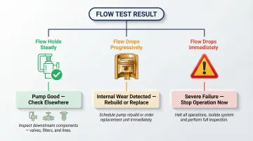
Interpretation:
- Flow holds steady up to rated pressure: Pump is good; fault is elsewhere in the system
- Flow drops progressively with pressure: Internal wear/bypass; pump needs rebuild or replacement
- Flow drops immediately at low pressure: Severe failure, likely damaged seals or pistons
For pressure-compensating pumps: Turn the compensator adjustment fully clockwise before the test to force the pump to behave as a fixed displacement unit. This ensures the pump delivers maximum volume throughout the test. Skipping this step causes the pump to de-stroke, producing falsely low flow readings.
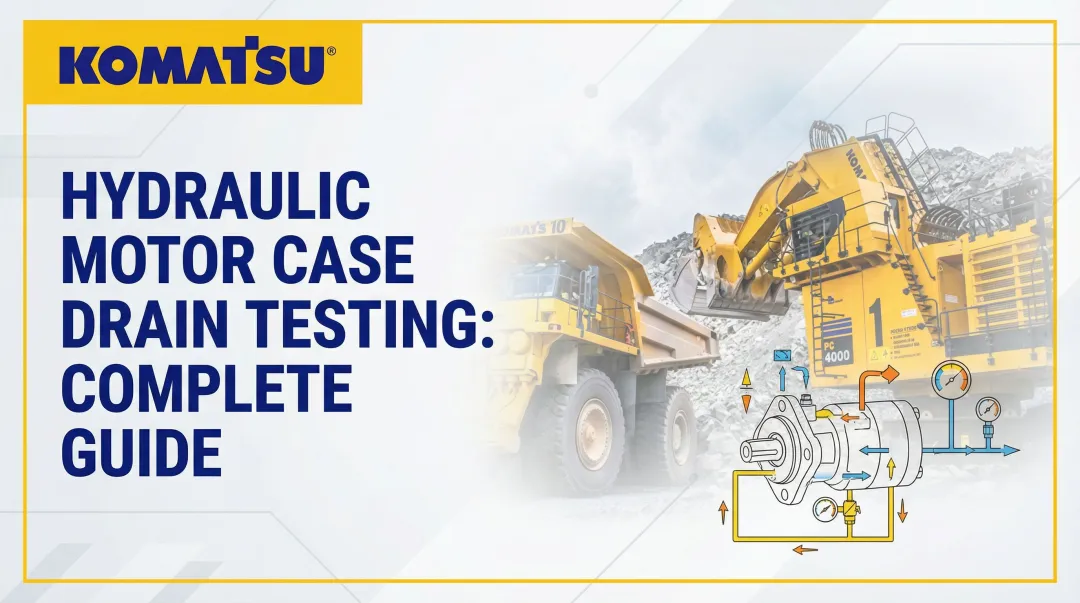
Step 4: Monitor Case Drain Flow and Temperature
As a pump wears internally, more oil bypasses across worn tolerances and returns through the case drain. Measuring case drain flow against published acceptable limits reveals how far wear has progressed.
Procedure:
- Install a flow meter in the case drain line
- Operate the system at normal temperature and pressure
- Measure case drain flow and compare to the pump's rated capacity
Threshold: If more than 10% of the pump's maximum output flows out the case drain line, the pump requires rebuild or replacement. For example, a 20 GPM pump with 2+ GPM case drain flow is at end-of-life.
Temperature monitoring: Rising case drain temperature is a secondary indicator of wear. Bypassed fluid drops from high pressure to low without doing useful work, converting that energy to heat. A case drain line running significantly hotter than the tank return line points to excessive internal leakage.
Step 5: Track Motor Current Draw
In electrically driven pumps, internal bypassing reduces the useful work the pump performs, which causes a measurable drop in motor current draw. A pump pulling less current than expected under load is a sign of internal leakage, not efficiency — the motor simply has less resistance to work against.
Procedure:
- Use a clamp-on ammeter to measure motor current draw at no-load
- Load the system to normal operating pressure and measure current draw again
- Compare readings to baseline or manufacturer specifications
Interpretation: A worn pump will show lower current draw under load because the motor is doing less work (the bypassed fluid is not being pressurized). Motor Current Signature Analysis (MCSA) can also detect pump wear, valve sticking, and cavitation by analyzing spectral sideband frequencies in the motor's current signature.
How to Interpret Hydraulic Pump Test Results
Even a badly worn pump can deliver near-rated flow when system resistance is low. Only a healthy pump can deliver rated flow at rated pressure; that's the pass/fail criterion of the relief valve flow test.
Diagnostic Framework
Flow steady under increasing pressure:
- Pump is good; fault is elsewhere in the system
- Check relief valve calibration, directional control valves, actuators, and filters
- Verify fluid condition and contamination levels
Flow drops progressively with pressure:
- Internal wear/bypass; pump needs rebuild or replacement
- Cross-reference with case drain flow and motor current draw
- Calculate volumetric efficiency: (Actual Flow ÷ Theoretical Flow) × 100
Flow drops immediately at low pressure:
- Severe failure, likely damaged seals, pistons, or valve plates
- Pump requires immediate replacement or rebuild
- Do not continue operating; continuing to run it will cause additional damage
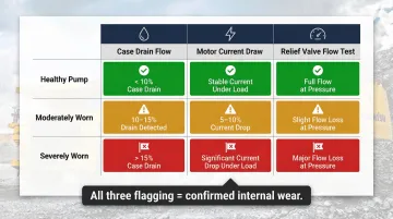
Cross-Referencing Indicators
No single indicator tells the whole story. A pump showing declining case drain flow, dropping motor current, and failing the flow test under pressure presents a consistent picture of internal wear. When only one indicator flags, look for a different root cause before condemning the pump:
- Relief valve set too low or worn internally
- Air contamination causing cavitation
- Blocked suction line reducing inlet pressure
- Incorrect compensator setting on variable-displacement pumps
Caution Against Premature Pump Replacement
Misreading test results—or skipping tests entirely—leads to expensive, unnecessary pump swaps. Hydraulic pumps range from $200 for small gear pumps to $20,000+ for large radial piston pumps, so the cost of misdiagnosis adds up fast. A weakly-set relief valve, air in the system, or a blocked suction line can each produce symptoms identical to a failing pump. Confirm the root cause before pulling the unit.
Key Factors That Affect Hydraulic Pump Test Accuracy
Fluid Temperature
Hydraulic oil viscosity changes with temperature, and testing a cold system produces different flow and pressure readings than a system at operating temperature. ISO 4409 mandates that diagnostic flow testing be conducted at controlled, stated fluid temperatures (for example, 50°C or 80°C).
Viscosity drops exponentially as temperature rises, which directly increases internal leakage. Always bring the fluid to normal operating temperature before recording test data.
Fluid Contamination and Condition
Degraded or contaminated fluid increases internal leakage and distorts efficiency readings. Check fluid condition before blaming the pump:
- Particle contamination (ISO 4406 cleanliness code)
- Water ingress (milky appearance, reduced lubricity)
- Chemical degradation (darkening, acidification, varnish formation)
Relief Valve Condition and Calibration
A worn or incorrectly set relief valve will vent flow before the pump reaches system pressure, making a good pump appear faulty. Always verify relief valve calibration as part of the diagnostic. Use a calibrated pressure gauge and adjust the relief valve to the correct cracking pressure before conducting the flow test.
Flow Meter Rating and Installation Direction
Using a meter not rated for the system's maximum pressure or flow, or installing it in the wrong flow direction, yields invalid results and poses a safety risk. Verify:
- Pressure rating exceeds system maximum
- Flow range matches expected pump output
- Installation direction matches flow arrow on meter body
- Proper sealing and torque on threaded connections
Pump Type (Fixed vs. Variable Displacement)
Variable displacement pumps require the compensator to be set to maximum displacement before flow testing. Failing to do this causes the pump to de-stroke and produce falsely low flow readings. Turn the compensator adjustment fully clockwise (or per manufacturer instructions) to force the pump to 100% displacement.
Because internal leakage acts as a fixed orifice, it remains constant regardless of displacement setting. The practical result: a pump might show 20% efficiency at 10% displacement but 92% efficiency at 100% displacement.
Common Mistakes and When to Call a Professional
The Most Common Testing Error: Replacing the Pump Before Testing
Hydraulic pumps range from hundreds to tens of thousands of dollars. A systematic test takes minutes and confirms whether the pump is the failure point before any parts are ordered or swapped. Replacing a pump without testing risks:
- Leaving the root cause unaddressed (contamination, valve failure, filter restriction)
- Destroying a new pump within hours or days
- Incurring emergency repair premiums unnecessarily
- Extending downtime while waiting for parts that weren't needed
Unsafe or Improvised Testing Setups
Improvised or unsafe testing setups—disconnecting lines under pressure, using uncalibrated gauges, bypassing safety valves—are dangerous and produce unreliable results. Always:
- Use proper flow meters rated for system pressure and flow
- Use certified pressure gauges with current calibration
- Follow manufacturer safety procedures and lockout/tagout protocols
- Never defeat safety interlocks or bypass relief valves during testing
When Professional Bench Testing Is Required
In-field testing is insufficient in these scenarios:
- Large-displacement pumps where on-machine testing cannot reach full rated power
- Post-rebuild verification requiring Statistical Process Control data against manufacturer specifications
- Inconclusive results where multiple system components are suspected
- High-pressure or high-flow systems that exceed portable test equipment capabilities
When bench testing is the right call, Hydrostatic Transmission Service rebuilds and tests pumps from Parker, Rexroth, Eaton, Sauer Danfoss, Hydreco, John Deere, and other major manufacturers to manufacturer specifications—backed by a 1-year warranty. Their Short-Time exchange program keeps downtime short: once testing confirms a pump needs replacement, you receive a quality-tested rebuilt unit while your core is processed.
Frequently Asked Questions
Can you bench test a hydraulic pump?
Yes, bench testing involves mounting the pump on a dedicated test stand connected to a hydraulic power unit, flow meters, and gauges to simulate operating conditions. It is the most controlled and accurate method, especially for post-rebuild verification of pumps that cannot be tested in-system.
How do you test hydraulic pump efficiency?
Volumetric efficiency is measured by comparing actual flow output to theoretical rated flow under load using a flow meter at the relief valve. Overall efficiency can also be calculated using the thermodynamic method by measuring input power, pressure differential, and temperature rise.
How do you check hydraulic pump pressure?
A calibrated pressure gauge is installed at the pump outlet (or in the pressure line), the system is brought to operating temperature, and pressure is read at no-load and under load. The reading is compared to the manufacturer's rated output pressure to confirm the pump is building adequate pressure.
What will happen if there is air trapped in the hydraulic system?
Trapped air causes cavitation (whining or knocking noise), erratic pressure, reduced flow, accelerated wear, and fluid aeration (milky appearance). During testing, air ingestion distorts readings and can produce false-negative results on an otherwise functional pump.
What are the key components to test in a hydraulic system?
Beyond the pump, a full system test should cover:
- Relief valve — pressure setting and seat condition
- Directional control valves — internal leakage
- Actuators — cylinders or motors for bypass
- Filters — differential pressure and restriction
- Fluid condition — contamination, aeration, viscosity
The pump is often suspected first, but is not always the source of degradation.
How much does a hydraulic test cost?
In-field flow meter testing costs a few hundred dollars in equipment if not already on hand. Professional bench testing service fees vary by pump size and complexity, but are consistently far less than the cost of unnecessary pump replacement or unplanned downtime.