Introduction
A hydraulic motor showing weak performance, loss of torque, or sluggish response is often written off as a system-wide problem — when the actual culprit is excessive internal leakage measurable right at the case drain line in under 15 minutes.
Misdiagnosis carries real costs. Replacing serviceable components wastes budget, and leaving a worn motor in service risks catastrophic failure that takes other system components with it. Unplanned downtime in industrial facilities averages $108,000 per hour, with emergency repairs running 150–200% more than planned maintenance.
That math makes a 15-minute test worth running.
This guide covers how case drain testing works, what flow rate thresholds indicate worn internal components, and how to act on the results before a failing motor damages pumps, valves, and hoses elsewhere in your system.
Key Takeaways
- Case drain flow measures internal leakage that reveals motor wear condition without full teardown
- A slow trickle is normal and lubricates internal components; excessive flow indicates worn parts reducing efficiency
- Disconnect the case drain line, route flow into a measured container, and run at operating conditions to benchmark against specs
- The 1-quart-in-15-seconds rule for drive motors and the 5% theoretical flow rule provide practical pass/fail benchmarks when manufacturer data is unavailable
- Failed motors require scheduled overhaul, professional rebuild, or short-time exchange to restore performance with minimal downtime
What Is a Hydraulic Motor Case Drain and Why Does It Matter?
The case drain line routes unavoidable internal leakage — fluid that bypasses piston seals and valve plates inside the motor — back to the hydraulic reservoir. This prevents internal case pressure from building to damaging levels that can rupture seals or crack housings.
Some internal leakage is by design. It lubricates critical rotating components including:
- Piston shoes sliding against the swash plate
- The cylinder block-to-valve plate interface
- Bearing surfaces and shaft seals
That lubrication depends on continuous flow through the drain line. A motor with zero case drain flow indicates a blocked drain — which can destroy the unit within hours.
Where Case Drain Fits in Your Hydraulic Circuit
In open-circuit systems, the case drain line runs directly from the motor housing back to the tank, separate from the main return line. In hydrostatic (closed-loop) transmissions, the situation becomes more complex: the charge pump relief often vents into the motor or pump case, which means case drain flow in those circuits includes more than just internal motor leakage. That distinction matters when you're evaluating test results.
Why Case Drain Testing Is Critical for Equipment Uptime
As internal components wear — valve plate faces, piston bores, cylinder barrel surfaces — leakage increases proportionally, reducing the motor's volumetric efficiency. A new axial piston motor typically runs at around 95% volumetric efficiency at rated speed and pressure.
When efficiency drops below 85-90%, more input flow is needed to produce the same output torque and speed.
Case drain testing quantifies this efficiency loss non-invasively. It's often faster and more accessible than full output flow testing because drain lines are easier to reach and flow volumes are smaller.
Real symptoms operators experience from excessive case drain flow:
- Loss of drive power and inability to maintain speed under load
- Slower-than-normal operation across all functions
- Inability to hold a load without drift
- Overheating as wasted energy converts directly into heat
Catching a motor trending toward the failure threshold early prevents collateral damage and replaces an unplanned breakdown with a scheduled swap — a significant difference in total downtime.
70% to 90% of hydraulic system wear and failure is contamination-related, often accelerated by metal debris from failing internal components circulating through the entire system.
What You'll Need: Tools and Safety Preparation
Required tools for a basic field case drain test:
- Combination wrench set
- Hydraulic cap-and-plug set to cap the disconnected hose
- Clean drain hose sized to fit the motor's case drain port
- Catch pan or graduated container of known volume (1-quart or 1-liter container)
- Stopwatch or phone timer
- Optional: clamp-on or inline flow meter for greater precision
Mandatory Safety Steps Before Starting
Equipment preparation:
- Chock all wheels to prevent machine movement
- Disengage the parking brake or disconnect the brake coil as directed by the service manual (so the machine remains stationary under drive input during testing)
- Ensure the machine is in a stowed/neutral position
- Confirm hydraulic fluid temperature is within normal operating range
One preparation step that's easy to miss: fluid temperature matters. Case drain flow should be measured with oil at rated viscosity — 50°C (about 120°F) is the industry reference standard for most mineral oil systems.
Cold oil reads lower and can mask a real problem. Hot oil gives artificially high readings. Either way, you get a false result.
Identify the correct case drain port versus the work ports (A and B) on the motor before disconnecting anything. Consult the machine's service manual for the specific drain port location and any model-specific precautions.
How to Test Hydraulic Motor Case Drain – Step by Step
This procedure applies to piston-type hydraulic motors used in drive, travel, and work circuits. Hydrostatic closed-circuit transmissions require additional consideration addressed in the next section.
Step 1 – Locate and Disconnect the Case Drain Line
Identify the case drain line on the motor (typically a smaller-diameter line compared to the high-pressure work ports). Carefully loosen and remove it, then cap the hose end immediately with a hydraulic plug to prevent contamination and uncontrolled fluid release.
Step 2 – Attach the Drain Collection Setup
Thread or push-fit a clean drain hose onto the now-exposed case drain fitting on the motor body. Route the other end of this hose into your graduated catch pan or container, positioning it so all discharged fluid is captured cleanly.
Step 3 – Bring the System to Operating Temperature
Start the machine and let it run until the hydraulic fluid reaches operating temperature. Cold oil produces artificially low leakage readings because viscosity drops as fluid warms — test on cold oil and you'll pass a motor that's actually worn. Verify temperature using the machine's gauge or an infrared thermometer on the reservoir.
Step 4 – Apply Load and Run the Test
With the machine stationary (wheels chocked, brake coil disconnected per service manual), engage the drive or work function. Stroke the joystick or lever to full speed for 15 seconds at full drive command. Make sure the motor is working under actual load, since drain flow rises with system pressure.
Step 5 – Measure and Record the Flow
At the end of the timed interval, stop the machine and measure the volume of fluid collected in the container. Convert to a flow rate (for example, 0.8 quarts collected in 15 seconds equals roughly 1.9 GPM). Record the following alongside your flow figure:
- Fluid temperature at time of test
- System pressure (if measurable)
- Machine operating conditions (load, speed, function engaged)
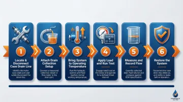
Step 6 – Restore the System
Remove the drain collection hose and reconnect the original case drain line securely to its fitting. Confirm all connections are tight, remove wheel chocks and restore the brake coil. Check fluid level in the reservoir and top up if necessary before returning the machine to service.
How to Interpret Case Drain Flow Results
Primary Benchmark: Manufacturer Specifications
Consult the machine's service manual or the hydraulic motor manufacturer's specifications for the exact acceptable case drain flow range — this is always the most reliable reference. If two identical motors are on the same machine (left and right drive motors), comparing the suspect motor's flow directly to the known-good motor's flow under the same conditions is a highly effective diagnostic technique even without a specification figure.
The "Trickle vs. Stream" Field Rule
When precise specs are unavailable, a slow trickle is normal and expected. When precise specs are unavailable, a slow trickle is normal and expected. A strong, sustained stream that fills a quart container in 15 seconds or less is a clear indicator the motor needs service, according to Genie's tech tips for wheel-type drive motors on boom lifts and similar equipment.
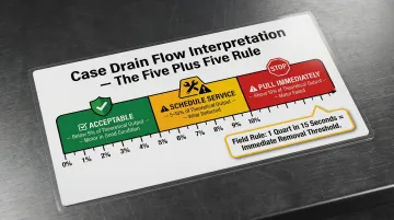
The "Five Plus Five Rule"
For estimating ballpark thresholds on piston-type motors when no spec is available:
- Calculate 5% of the motor's theoretical flow (displacement × rated RPM) as the "good" baseline drain flow
- Add that same 5% value again to establish the "bad" threshold
- Flow below the first figure indicates acceptable volumetric efficiency
- Flow between the two values indicates wear requiring scheduled service
- Flow above the second figure indicates the motor should be pulled immediately
Hydrostatic Closed-Circuit Complication
In a closed-loop hydrostatic transmission, the charge pump relief valve typically vents into the case of either the pump or the motor. This means total case drain flow from the shared drain line includes charge pump relief flow — often 10 GPM or more — on top of actual internal leakage, as Hydraulic Supermarket explains in their case drain flow assessment guide.
In these systems, the motor and pump case drains must be isolated from each other and the charge relief dump point identified before any valid conclusions can be drawn.
Variables That Affect Reading Accuracy
Hold these consistent between tests:
- System pressure — drain flow scales significantly with pressure
- Fluid temperature/viscosity — always test at rated operating temperature
- Motor speed — maintain consistent RPM during measurement
- Displacement setting — for variable motors
Testing at low pressure or low temperature will understate actual leakage — skewing results toward a false pass.
What to Do When a Motor Fails the Case Drain Test
If case drain flow exceeds acceptable limits, the motor should be removed from service before operating conditions worsen. Continued operation accelerates wear on the valve plate, cylinder barrel, and piston shoes, and risks contaminating the entire hydraulic system with metal debris. A basic pump or motor replacement costing $1,000 can escalate to $4,000–$6,000 when contamination requires complete system cleaning.
Three Options for Failed Motors
1. Schedule a professional rebuild — The motor is disassembled, worn components replaced, and the unit tested back to manufacturer specifications. Appropriate when time allows.
2. Source a remanufactured replacement unit — Remanufactured units reduce costs by up to 50% compared to buying new parts and carry the same warranty as new parts.
3. Use a short-time exchange program — A pre-rebuilt, tested, and warranted unit is shipped immediately to minimize downtime. This is the fastest path back to operation for critical equipment.

Hydrostatic Transmission Service Exchange Program
For operators who need the exchange program option, Hydrostatic Transmission Service runs a Short-Time program built specifically to get failed units back in service fast. Each replacement ships as a pre-rebuilt, tested unit backed by a 1-year warranty.
HTS brings over 100 years of combined experience rebuilding hydraulic and hydrostatic units to manufacturer specifications. Quality control relies on a Statistical Process Control System that flags deviations before a unit ships — catching what visual inspection routinely misses.
Contact HTS at (800)-361-0068 or sales@htsrepair.com to discuss exchange or rebuild options.
Frequently Asked Questions
Does a hydraulic motor need a case drain?
Yes. Piston-type hydraulic motors require a case drain line to return internal leakage fluid to the reservoir and prevent case pressure from building to levels that damage shaft seals or piston assemblies. A blocked or missing case drain line is a serious fault that can destroy the motor.
Should oil come out of the case drain on hydraulic motors?
Yes. A small, steady trickle of oil is normal and confirms the motor's internal components are being lubricated. The concern is excessive flow, which points to internal wear or damage.
How much case drain flow is too much?
Always start with the manufacturer specification. In the field, the 1-quart-in-15-seconds rule is a common threshold for drive motors; when no spec is available, the Five Plus Five Rule (flow exceeding ~10% of theoretical output) provides a reliable ballpark for piston motors.
What is a case drain in a hydraulic pump?
A case drain in a hydraulic pump routes internal leakage from the pump housing back to tank, the same function as in a motor. Measuring pump case drain flow is a valid method for assessing volumetric efficiency, though variable displacement pumps can see high transient flows that complicate permanent meter installation.
Can I test case drain flow without a flow meter?
Yes. Route the case drain into a graduated container, run the machine for 15 seconds at full operation, measure the collected fluid, and calculate GPM. A bucket and stopwatch are all you need for a field pass/fail check.
What causes excessive case drain flow in a hydraulic motor?
Main causes include worn or scored valve plate and cylinder barrel faces, worn piston-to-bore clearances, damaged piston shoes or swash plate, and contaminated hydraulic fluid that accelerates internal wear. All result in fluid bypassing the working circuit and escaping into the case.