Introduction
Axial piston pumps drive the hydraulic systems in construction excavators, agricultural machinery, industrial equipment, and aerospace applications. These pumps convert mechanical input from engines or motors into controlled, high-pressure hydraulic output that drives every powered movement a machine makes.
Despite their widespread use, many operators and technicians don't fully understand how these pumps work — and that gap has consequences. Technicians miss early degradation signs, select the wrong replacement, or pull a pump that still had service life left.
When a pump starts losing pressure or responding inconsistently, knowing what's happening inside lets you act before downstream components take the hit.
This guide breaks down how an axial piston pump works in practice—covering core components, operating sequence, displacement control methods, and the equipment these pumps power across industries.
Key Takeaways
- Axial piston pumps convert mechanical rotation into controlled hydraulic flow using pistons arranged parallel to the drive shaft
- Swash plate angle controls piston stroke length—changing it adjusts fluid displacement per rotation
- Pistons draw fluid in during the outward stroke and push pressurized fluid out during the inward stroke
- Variable displacement pumps match output to real-time load demand, using less energy than fixed displacement designs
- Used across construction, agriculture, manufacturing, and aerospace where high-pressure, precisely controlled hydraulic flow is critical
What Is an Axial Piston Pump?
An axial piston pump is a positive displacement pump in which multiple pistons are arranged in a circular array within a rotating cylinder block. The pistons move parallel to (axial to) the drive shaft. That axial alignment gives the pump its name and sets it apart from radial piston designs, where pistons extend outward like spokes.
Unlike gear or vane pumps that deliver fixed flow with limited pressure capability, axial piston pumps operate at high pressures (250–350 bar or 3,600–5,100 psi), handle variable loads, and adjust output flow on demand. That combination is why you'll find them powering excavator arms, agricultural drive systems, and industrial presses where precision and power must coexist.
What an axial piston pump is not:
- Not a centrifugal pump (which moves fluid by velocity, not displacement)
- Not the same as a radial piston pump (different piston arrangement)
- Not always variable—fixed displacement versions exist with locked swash plates
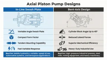
Two Main Design Variants
In-line swash plate design (most common):
- Cylinder block parallel to drive shaft
- Pistons bear against angled swash plate
- Dominates mobile and industrial equipment due to compact size and through-drive capability
- Fast variable response times
- Excellent for mounting multiple pumps in tandem
Bent-axis design (higher efficiency, higher cost):
- Cylinder block angled up to 40° relative to shaft
- Direct connection to shaft flange reduces lateral forces
- Superior mechanical efficiency and lower friction
- Preferred for continuous heavy-duty industrial applications
- Limited through-drive capability
Choosing between them comes down to application demands. Industry analysis confirms that swash plate designs dominate construction and agricultural equipment because of compact integration and variable displacement compatibility, while bent-axis pumps earn their place in continuous high-pressure industrial operations where the efficiency gains justify the added complexity.
How Does an Axial Piston Pump Work?
An axial piston pump operates through a continuous rotational cycle where each piston completes a full stroke—drawing fluid in during one half and pushing it out under pressure during the other. The valve plate and swash plate work together to control timing and displacement.
Initiation: Starting the Pumping Cycle
The cycle begins when the drive shaft (connected to an engine, motor, or prime mover) rotates the cylinder block, causing all pistons to rotate around the central axis. Because the swash plate is set at an angle, pistons are mechanically forced to move in and out of their cylinder bores as they rotate—this is the fundamental activation mechanism.
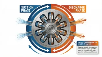
As each piston moves outward (away from the valve plate), it creates a low-pressure void in the cylinder bore. This void draws hydraulic fluid in through the inlet port of the valve plate—the suction phase that fills the chamber and prepares the piston for compression.
The valve plate features two kidney-shaped openings covering nearly 180 degrees each—one for suction, one for discharge. The timing of when a displacement chamber transitions from low-pressure to high-pressure port is critical for proper pressurization.
Core Operation: Building and Delivering Pressure
As the cylinder block continues rotating, each piston transitions from outward stroke to inward stroke. The swash plate forces the piston back toward the valve plate, compressing the trapped fluid and pushing it out through the discharge port at high pressure. Because this is positive displacement, each full stroke moves a predictable, set volume of fluid.
Swash plate angle controls output volume: The steeper the angle, the longer each piston's stroke and the greater the volume displaced per revolution. At zero angle (perpendicular to the shaft), pistons have no stroke and the pump produces no flow. As the angle increases—typically up to 15–17 degrees or more—stroke length grows proportionally, allowing larger fluid volumes per rotation.
Industry convention uses an odd number of pistons—typically 7, 9, or 11—to reduce flow pulsation and torque ripple. Each piston contributes to a continuous overlapping discharge sequence, maintaining steady hydraulic pressure rather than pulsed bursts. Theoretical analysis shows that flow variation for an odd-piston pump equals that of a pump with twice as many pistons. Even-numbered configurations cause symmetrical pistons to discharge simultaneously, producing torque fluctuations and uneven flow.
Major manufacturers follow this convention, with most designs running 7-, 9-, or 11-plunger structures:
- Kawasaki K3V and K5V series
- Bosch Rexroth A10VSO series
- Rexroth A1VO series
Managing pressure transitions: To prevent sudden loading, overpressurization, and cavitation, valve plates incorporate relief grooves attached to the kidney ports. These grooves allow small flow transfer areas before chambers fully open to kidney ports, controlling compression and expansion rates—a primary method for reducing fluid-borne and structure-borne noise.
Regulation and Control: Maintaining Stable Output
Two control strategies keep output stable under varying demand:
Pressure compensation — A control valve monitors system pressure and automatically adjusts the swash plate angle when the set threshold is reached (commonly 280 bar or 4,000 psi). This prevents over-pressurization without a separate relief valve doing continuous work, reducing heat and improving efficiency.
Load-sensing control — The pump receives a signal from downstream pressure demand and adjusts swash plate angle to produce only the flow needed, plus a small offset (typically 14–25 bar). Running at maximum pressure when the load needs only partial flow wastes energy; load-sensing eliminates that waste.
When internal components wear—scored cylinder bores, damaged piston shoes, or a deteriorated valve plate—pressure compensation becomes inconsistent and system behavior turns unpredictable. That pattern signals degraded tolerances and the need for rebuild or exchange to restore accurate regulation.
Measuring case drain flow is a primary diagnostic method. While a new pump may achieve 95% volumetric efficiency at rated speed and pressure, excessive case drain flow (exceeding 5–10% of nominal flow) indicates significant internal wear and impending failure.
Output and System Integration
The pump delivers pressurized hydraulic fluid at a controlled flow rate to downstream actuators: cylinders that produce linear motion, motors that produce rotational motion, and control valves that direct flow to specific functions. Every powered movement the machine makes starts here.
Consistent, stable flow means cylinders extend smoothly, motors hold torque under load, and the machine responds predictably. When pump output degrades, the effects travel downstream fast—sluggish response, erratic movement, and accelerated wear on actuators are early signs that the pump itself needs attention.
Fixed vs. Variable Displacement: Why It Matters in Practice
The swash plate angle determines how a pump handles changing load conditions — and the choice between fixed and variable displacement has real consequences for energy use, heat generation, and operating cost.
Fixed displacement locks the swash plate at a set angle, delivering the same volume every revolution regardless of demand. Simple, durable, and cost-effective — but excess flow must be bypassed or unloaded when full output isn't needed, generating heat and wasting energy. It suits applications with constant, predictable load conditions.
Variable displacement adjusts the swash plate angle dynamically in response to system pressure or load signals, delivering exactly the flow the system needs at any moment. This makes it far more efficient in equipment with fluctuating loads — excavators, combine harvesters, and industrial presses where demand shifts constantly during work cycles.
Efficiency Gains: The Data
Research on variable displacement advantages shows substantial fuel and energy savings:
- Tractors: 10-15% reduction in fuel consumption per operating hour in mixed use (Bosch Rexroth A1VO vs. fixed gear pump)
- Forklifts: Expected savings of 0.7 liters per hour based on standard load profiles
- Industrial applications: Up to 10% higher efficiency, with case studies showing 15% reduction in energy consumption
- Heat generation: Reduced wasted bypass flow lowers heat generation, potentially allowing downsizing of oil coolers
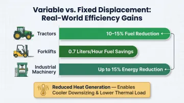
Variable displacement pumps achieve these savings primarily during partial-load operations, where fixed pumps continuously generate full flow at maximum pressure, forcing the system to dissipate that excess energy as heat.
The control method you select directly determines how well those efficiency gains translate to your specific application.
Control Methods Available
| Control Method | How It Works | Best For |
|---|---|---|
| Pressure-Compensated | Senses outlet pressure via compensator spool; destrokes to zero when pressure limit (e.g., 280 bar) is reached | Fixed-pressure systems, overload protection |
| Load-Sensing (LS) | Reads load signal line; maintains constant Δp of 14-25 bar to match flow precisely to demand | Mobile equipment with variable actuator loads |
| Electronic/Proportional | Proportional solenoid adjusts displacement per electrical input (0-10V or 4-20mA); increasingly replacing hydro-mechanical compensators | Advanced automation, precision control applications |
| Manual/Mechanical | Handwheel or linkage adjusts swash plate angle steplessly; operator-controlled | Simple systems requiring manual override or low-cycle-count adjustment |
Each method trades off response speed, precision, and maintenance complexity differently — making the right match as important as the pump type itself.
Where Axial Piston Pumps Power Equipment
Primary Industrial and Mobile Applications
Construction machinery:
- Excavators, wheel loaders, cranes
- Drives boom cylinders, swing motors, and track drives simultaneously under variable loads
- The Komatsu PC200-8 uses variable displacement piston pumps for boom, arm, and bucket circuits
Agricultural equipment:
- Combines, tractors, harvesters
- Powers steering, header drives, and attachment functions
- John Deere 6R/7R series use closed-center, pressure and flow-compensated axial piston pumps
Industrial manufacturing:
- Hydraulic presses, injection molding machines, metal forming equipment
- High-pressure precision control is critical
- Variable displacement with pressure compensation delivers efficiency and control
Aerospace systems:
- Jet aircraft hydraulic systems for flight controls and landing gear
- Commercial jets (Airbus A320/A330, Boeing 737/777) operate at 3,000 psi (207 bar)
- Engine-driven and electric motor-driven inline piston pumps
Operating Conditions Where Axial Piston Pumps Excel
High-pressure systems:
- Typically operating above 200 bar (3,000 psi)
- Major OEM pumps rated for 350 bar (5,100 psi) continuous, 400-420 bar peak
Variable flow applications:
- Equipment requiring flow matched to changing loads
- Continuous-duty operations where efficiency and heat management are priorities
Comparison to other pump types:
| Pump Type | Best For |
|---|---|
| Gear pumps | Fixed, low-pressure applications |
| Vane pumps | Mid-pressure, lower-contamination environments |
| Axial piston pumps | High-pressure, variable flow, demanding duty cycles |
Market Growth and Adoption
Global demand for axial piston pumps is rising as mobile equipment electrification and energy efficiency requirements push adoption of variable displacement technology:
- Market size projected to grow from $6.8 billion (2024) to $9.5 billion (2030) at 5.6% CAGR
- Mobile equipment (construction, agriculture, mining) represents the largest application segment
- Shift toward energy-efficient hydraulics drives adoption of variable displacement technology
Conclusion
The axial piston pump converts mechanical rotation into high-pressure hydraulic flow through a precisely coordinated cycle of piston stroke, valve plate timing, and swash plate angle control. Understanding this sequence explains why pump condition directly determines the responsiveness, efficiency, and power output of every system it drives.
Operators and technicians who understand how the pump works are better positioned to recognize early warning signs of degradation—sluggish response, inconsistent pressure, unusual noise—and act before downstream components are affected. When an axial piston pump reaches the end of its service life, a professionally rebuilt unit tested to manufacturer specifications restores full system performance and keeps downtime to a minimum.
Hydrostatic Transmission Service rebuilds axial piston pumps from major manufacturers including Rexroth, Parker, Eaton, Vickers, Kawasaki, Danfoss, and Komatsu. Every rebuild is backed by:
- Statistical Process Control testing — quality data compared directly against manufacturer specifications
- One-year warranty on all rebuilt units
- Short-Time exchange program — quality-tested units ship quickly to reduce equipment downtime
- Installation advice from trained technicians to support correct reinstallation
Frequently Asked Questions
How does a variable displacement axial piston pump work?
It uses a movable swash plate whose angle is adjusted by a control mechanism—pressure compensator, load-sensing valve, or electronic actuator. When the angle increases, piston stroke lengthens and flow increases; when the angle decreases, flow drops, allowing the pump to match output to real-time system demand.
How long do axial piston pumps typically last?
With proper filtration and maintenance, axial piston pumps commonly run 8,000–15,000 operating hours before requiring rebuild or replacement. Contaminated fluid is the leading cause of premature failure, making clean hydraulic fluid the single most important factor in extending service life.
What is a variable axial piston pump?
A variable axial piston pump has a movable swash plate that lets operators change displacement during operation. A fixed displacement pump locks the swash plate at a set angle, so output stays constant per revolution regardless of system demand.
What is an axial piston pump used for?
Axial piston pumps power hydraulic systems in construction equipment (excavators, cranes), agricultural machinery, industrial presses, jet aircraft hydraulic systems, and various manufacturing applications. They're chosen for applications requiring high pressure (above 200 bar), variable flow capability, and reliable continuous-duty performance.
What is the axial displacement of a pump?
Axial displacement refers to the volume of fluid displaced per shaft revolution, determined by the piston stroke length. In a variable displacement pump, this is set by the swash plate angle—a higher swash plate angle means a longer piston stroke and greater displacement per revolution.
What are the signs of a failing axial piston pump?
Watch for these warning signs:
- Loss of system pressure or sluggish actuator response
- Unusual grinding or whining noise under load
- Rising hydraulic fluid temperature
- Metal particles or contamination in the fluid
Any of these points to internal wear on pistons, cylinder bores, or the valve plate—warranting inspection or rebuild.